- Sign In
- |
- Sign Up
- |
- My Quote (0)
- |
- CART (0)

Offering you an extensive selection of the best brands and products for your thermography needs.

Keeping your toolbox equipped with the reliable tools that you need to get the job done right.

Offering you an extensive selection of the best brands for substantial savings on your energy consumption costs.

We've made it easy for you to find the data logger you need for your application, at your price point.

Our experts offer you the products and training needed for you to do your work safely. We’ve got you covered.

Providing the industry’s top brands and products for your laboratory supply needs.

Quickly find answers by clicking on the subject of your question below. As always, if you need additional help resolving any product issues, feel free to contact our support team.
You do not need to. The APM continually looks at the input and if it sees an AC voltage (both positive and negative voltages) it will automatically switch into AC mode and will calculate and display the true RMS voltage. If no positive and negative voltages are detected then the APM will assume that the input is DC and will display the average voltage.
Yes. The APM samples the voltage input at a rate of 62KHz. The samples then go through a digital low-pass filter before being displayed. The low pass filter allows frequencies below about 5KHz to pass through but block higher frequencies.
Yes. From firmware revision 6, the APM will calculate and display the true RMS voltage – even if the waveform is non-sinusoidal and/or asymmetric.
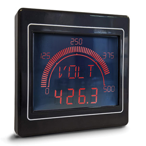
To maximize accuracy the Volt Meter incorporates a programmable gain amplifier (PGA). This amplifier acts rather like an iris and automatically opens and closes depending on the input voltage. The PGA has 16 different ranges as shown here.
As an example, with a 110V input the APM will be on range 12 and the resolution will be 81.6mV. The worst case error will be 1.6V.
| Volt Meter | ||||
|---|---|---|---|---|
| Range Number | Full Sacle | Resolution | Rated | Maximum |
| (V) | (mV) | Accuracy | Error(V) | |
| 1 | 8 | 4.2 | 1% | 0.1 |
| 2 | 11 | 5.6 | 0.1 | |
| 3 | 13 | 7.1 | 0.1 | |
| 4 | 16 | 8.5 | 0.2 | |
| 5 | 19 | 9.8 | 0.2 | |
| 6 | 21 | 11.3 | 0.2 | |
| 7 | 27 | 14.1 | 0.3 | |
| 8 | 35 | 18.3 | 0.3 | |
| 9 | 51 | 26.7 | 0.5 | |
| 10 | 75 | 39.4 | 0.7 | |
| 11 | 107 | 56.3 | 1.1 | |
| 12 | 155 | 81.6 | 1.6 | |
| 13 | 224 | 117.9 | 2.2 | |
| 14 | 324 | 170.5 | 3.2 | |
| 15 | 471 | 247.9 | 4.7 | |
| 16 | 780 | 380.3 | 7.8 | |
You can connect the Amp Meter directly to your circuit to measure AC or DC currents up to 5A on circuits carrying less than 42V AC/DC.
You can connect a CT (current transformer) directly to the meter to measure AC current up to 10,000A. When using the Amp Meter ensure any CT has a maximum output of 5A and is 1% accurate, therefore the reading is accurate to +/- 50mA. When selecting a CT, use one with a primary that matches your maximum input and a secondary (output) of 5A.
You can configure the CT ratio using the DIP switches on the rear of the APM or alternatively using the APM configurator software, however we would recommend for most applications using the CT Meter, a model developed specifically for use with current transformers.
The Amp Meter is a general purpose current meter that can be used for measuring currents in a wide range of applications. The CT Meter has been optimized for use with external CTs. The CT Meter can only be used to measure AC currents using a CT and offers improved accuracy over the Amp Meter.
We have developed the Shunt Meter specifically for use with current shunts.
The Amp Meter can be affected by magnetic interference from strong magnets and conductors carrying high voltages. To ensure that these do not affect the accuracy of the meter please ensure that these are kept at least 6 inches away from the meter.
0.002 ohms
The minimum recommended CT rating is 1VA
No. The Process Meter has two inputs but you can only use one of them at a time. You can connect both inputs of the Process Meter to your circuit but only the selected unit will be used. The other input is ignored.
The Amp Meter can measure bi-directional current flow (-5A to +5A) with both AC and DC currents. The Process Meter can only measure DC uni-directional currents (0 to 50mA). The Process Meter is also more accurate than the Amp Meter and supports non-linear conversion.
The Process Meter includes a 20 point linearization table that can be used to correct for non-linear sensors such as thermocouples and pressure transducers. This feature is accessible directly from the APM configuration software.
The Amp Meter is a general purpose current meter that can be used for measuring currents in a wide range of applications. The CT Meter has been optimized for use with external CTs. The CT Meter can only be used to measure AC currents using a CT and offers improved accuracy over the Amp Meter.
0.002 ohms
Minimum recommended CT rating is 1VA
We are constantly developing new models so the list keeps on growing. To view our current range please visit our APM page. If you have a specific application and cannot find the perfect meter, then contact us to discuss your requirements further.
No – please make sure you purchase the correct model for your application.
The only difference is that Output models have two physical outputs. These can be configured to be either digital (open collector) or analogue. No Output models do not have these outputs. Both Output and No Output models have alarms that can be configured to change the backlight and message when the input signal is on or out of range.
No. Each model is factory built with either a positive LCD or a negative LCD and the LCD cannot be changed in the field.
You can configure the backlight color as well as when it’s on, off and flashing using the APM configuration software. You can configure the backlight to:
The positive LCD has black digits and a bright background. The digits are readable in bright sunlight with the backlight on or off.
The negative LCD has bright digits and a black background. The display offers the highest contrast when used indoors. The digits are only readable when the backlight is on.

Positive Display for Outdoors
Negative Display for Indoors
Yes. For example, to show a bar graph that goes from -10 to +10 you need to complete the following steps in the Display Range section of the configuration software:
Once downloaded to the APM the bar graph will go from -10 to +10 with a center zero

This depends on the LCD that you have chosen. Positive LCDs are very readable in direct sunlight, but you will not be able to see the backlight color (the sun is so much brighter than any LEDs we can get our hands on!). Negative LCD are readable outdoors but not in direct sunlight.
Yes but you must only connect APMs to the AC supply. Also remember to connect the COM terminal on the APM to the same 0V/GND as your output.

Each APM will consumes 1.6W worst case. This assumes that the backlight is on full intensity and both analogue outputs are sourcing 20mA. The table below shows the maximum current required at various PSU voltages:
| PSU Voltage | Max Current (mA) |
|---|---|
| 12 | 133 |
| 15 | 107 |
| 24 | 67 |
Yes you can. When using a DC supply, just makes sure that the power supply you use is rated sufficiently to power all the APMS. Each APM draws a maximum of 1.6W. In the special case of using an AC supply and an APM with outputs you can connect multiple APMs to the same supply but you must not connect any other device to the same AC supply.
Yes, but please make sure you purchase a model with outputs. Depending on the voltage and power requirement of your warning light you may need some additional components (such as a relay or power transistor) to interface between the APM and your warning light.
The maximum current that the APM can sink is 500mA. The APM can therefore be connected to a load of up to 12W. Please note that the maximum voltage that can connected to the outputs is 24V.
Yes but not directly. The USB port can only to be used to configure the APM. If you want to look at live data then you need purchase an APM with outputs and then configure one of them to ‘Analog’. The APM will then output a current in the range of 4 to 20mA that is proportional to the displayed value on the APM. If you want to view this information on a computer then you will also need to procure a 4-20mA interface for your computer.
The APM outputs are only active when the condition is true. If you want to latch the output you need to connect a latching relay to the output of the APM. Please remember to fit a protection diode across the relay coil to prevent the back EMF from the coil damaging the APM.
To output 4-20mA on SP1 terminal, use the APM Configurator Software. Make sure you select the ‘Alarm 1’ tab (Alarm 1 tab controls SP1 output and Alarm 2 tab controls SP2 output). Then:


The 4-20mA output is a current source. The output will deliver a current between 4mA and 20mA into a maximum resistance of 250 ohms. Please remember to enable “analogue output” using the APM Configurator as all outputs default to digital.
Every APM comes with 15 pre-configured settings and these can be selected using the DIP switch on the rear of the APM. Please refer to your model’s user guide for a list of switch positions. Custom configurations can be created and downloaded to the APM using the freely available APM configuration software. Contact our expert for more information.
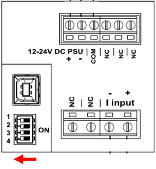
All APMs are shipped from the factory in auto-ranging mode. If you have changed the configuration and want to return back to auto-ranging then please make sure that all the DIP switches on the rear of the unit are pointing to the left (away from the screw terminals) as shown below. You will then need to run the APM configuration software, select ‘Auto Ranging’ and then ‘Write Configuration to APM.’

To connect the APM to a PC you will need a standard USB AB cable. The cable can be purchased from most electrical distributors or alternatively directly from Trumeter. The Trumeter part number for the cable is 022128-01.
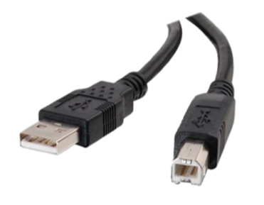
The APM has a Type B USB socket and you can use standard off the shelf adapters to convert this to a different type if you want.
You can connect multiple APMs to your computer but you can only program one of them at a time.
By default the display scalar is set to x1 and one unit of measure on the input equals one unit of measure on the display. As an example if you have a VOLT model and ’Display Scalar’ is set to x1 then 1 volt on the input would equal 1 volt on the display. However, in certain applications, you may want to apply a correction factor to the displayed value. As an example if you want 1 volt on the input to equal 10 volts on the display then all you need to do is select ‘User’ and enter 10 in the Scale box. Similarly if you want the displayed value to be the input value plus 3 volts then enter 3 in the Offset box. If you set both a Scale and an Offset then APM will apply the Offset first followed by the Scale. For example, applying a Scale of 0.01 and an Offset of 2 will result in the values to the right.
In the example here, applying 20V to the meter the displayed value would be (20V + 2) x 0.01 = 0.22V.
| Input | Displayed Value |
|---|---|
| 0 | 0.02 |
| 10 | 0.12 |
| 20 | 0.22 | 30 | 0.32 | 40 | 0.42 | 50 | 0.52 |
Yes you can. Just connect the meter that you want to copy to your computer and run the APM Configurator software. Select APM – Read Configuration from APM. Now select File – Save Configuration File to save a copy of the configuration on your computer then disconnect the APM and close down the APM Configurator. Now connect the meter that you want to configure and run APM Configurator. Select File – Load Configuration File to load the original configuration file and then select APM – Write Configuration to APM.
Yes. Click on File – Save Configuration file. You can also read the configuration from an APM. Just click on APM – Read Configuration from APM.
You can change the configuration as many times as you wish. You just need to connect the APM to your computer and download a new configuration. Downloading a new configuration will automatically overwrite the old configuration.
The configuration is stored in FLASH memory which can be reliably overwritten at least 1000 times.
You can either use the DIP switches on the rear of the APM or you can use the APM Configurator Software.
Using DIP Switches
The table to the right shows the various switch positions. Lines 5-16 are for use with external 5 amp CTs.
Using the APM Configuration Software
Make sure that all the DIP switches are in the OFF position (to the left pointing away from the screw terminals). Under ‘External Sensors’ select ‘CT’ and then enter the primary (input) and secondary (output) currents of your CT. In the example below the CT has an input of 300A and an output of 5A (i.e. 300:5).

| Sw Pos | Measured | Bar Graph | Display Value | |||
|---|---|---|---|---|---|---|
| Item | 1234 | Value | Min | Max | Format | Max |
| 1 | 0000 | Custom (Defined in Software Application) | ||||
| 2 | 1000 | Auto Raging | ||||
| 3 | 0100 | 4 A | 0 | 4 | #.### | 5.000 |
| 4 | 1100 | 5 A | 0 | 5 | #.### | 5.000 |
| 5 | 0010 | 10 A | 0 | 10 | ##.## | 10.00 |
| 6 | 1010 | 20 A | 0 | 20 | ##.## | 20.00 |
| 7 | 0110 | 40 A | 0 | 40 | ##.## | 40.00 |
| 8 | 1110 | 50 A | 0 | 50 | ##.## | 50.00 |
| 9 | 0001 | 60 A | 0 | 60 | ###.# | 60.0 |
| 10 | 1001 | 80 A | 0 | 80 | ###.# | 80.0 |
| 11 | 0101 | 100 A | 0 | 100 | ###.# | 100.0 |
| 12 | 1101 | 200 A | 0 | 200 | ###.# | 200.0 |
| 13 | 0011 | 400 A | 0 | 400 | #### | 400 |
| 14 | 1011 | 600 A | 0 | 600 | #### | 600 |
| 15 | 0111 | 800 A | 0 | 800 | #### | 800 |
| 16 | 1111 | 1000 A | 0 | 1000 | #### | 1000 |
By default the APM will display the reading on the four digit display to maximum resolution possible by automatically moving the decimal point to the right and left as the input signal changes. In some applications this might not be desirable and hence Limit Decimal Places allows you to limit the maximum number of decimal places that the APM will display. As an example if you select ‘1 (0.0)’ then the APM will display the measured value to no more than one decimal place.
The “Display Peak Bar” provides a visual indication of the average peak value on the bar graph display similar to what’s seen on a graphic equalizer. The duration the peak bar is visible is configurable from a few seconds to a few minutes by adjusting the ‘Peak Bar’ slider on the Response tab. Alternatively, if you want the Peak Bar to be latched on and show the maximum value since the unit was reset, click ‘Peak Hold’.
There are two ways: either by power cycling the APM or by using an external switch connected between the COM terminal and the RST terminal on the rear of the unit.

The display Zero function allows you to display zero when the input is below a specific value. This is useful in situations where there is noise around zero and you do not want to display this on the APM. As an example if you are monitoring a 600VAC circuit you may want to set Display Zero to 10 so that the meter will display 0.000 volts when the input is below 10 volts.
You can configure the APM from your desk. Just connect the APM to your computer using USB. You do not need an external power supply as the APM will draw its power from the USB port. When the APM is powered from USB it will show ‘USB’ on the display. In this mode you can upload and download new configurations to/from the APM but the APM cannot take any measurements or drive any alarms or outputs.
The screw terminals can accept cables up to 3.3mm2 / 12AWG.
To reset the APM disconnect power for three seconds.
To restore the APM back to factory defaults connect the meter to your computer and run the APM configurator. Select your meter and then select File – Load factory defaults. Then select APM – Write Configuration to APM.
The default backlight color is white. You can change the default backlight color using the APM configuration software.
No – The APM configuration software is free. Contact our expert for more information.
No – You can run the APM configuration software without needing to connect an APM. You can open, edit and save configuration files on your machine without needing to connect an APM.
To do this, run the configuration software and click ‘Configure APM.’ A list of models should appear. If the model that you want to configure is not shown in the list then click on ‘Download All APM Models’ and the software will automatically download all models from our update server. Please note than an internet connection is required to download new models.
Click on the required model from the list and then click ‘Configure.’


To enable custom settings on the APM please make sure that all the DIP switches on the rear of the unit are pointing to the left (away from the screw terminals) as shown here.
Please refer to your company’s IT policy.
The APM is rated for IP65; NEMA4 and NEMA12 from the front. A sealing gasket is supplied with each APM and the APM must be installed correctly. Please follow the installation instructions carefully especially in terms of the panel cut out dimensions.
The panel cut-out needs to be 68mm x 68mm (-0mm; +0.7mm) / 2.68” x 2.68” as per DIN 43718 and IEC61554.
The APM has been designed to meet both DIN 43718 and IEC61554.
Every APM comes with 15 pre-configured settings and these can be selected using the DIP switch on the rear of the APM. Please refer to your models user guide for a list of switch positions. Custom configurations can be created and downloaded to the APM using the freely available APM configuration software.
The APM is constructed from UV resistant plastic and can operate in temperatures from -10 deg C to +60 deg C. The front of the meter is fully sealed but an additional enclosure is required to protect the rear from the elements. Care needs to be taken in the design of the enclosure to ensure that the environment inside the enclosure does not exceed 85% humidity non-condensing.
This varies model by model but typically is about 180g (0.4 pounds).
The APM is supplied with a mounting clip. The meter is first installed through the front of the panel and then the mounting clip is installed from the rear of the meter.
Yes.
Yes. The APM meets all the requirements of The Restriction of Hazardous Substances Directive 2011/65/EU (RoHS 2).
Yes. The APM is UL and cUL listed for Open-type Measuring and Testing Equipment E469787.
All APMs are certified to IEC61010-1 and are CE marked.
Please check with your IT department as you may have a firewall or anti-virus product that may be blocking the process. Please try disabling your anti-virus during the install or configure your firewall to allow access to the following addresses:
To automatically check for updates every time that the APM configuration is run select Updates – Automatically Download Updates. Alternatively, to manually check for updates, select Updates – Download Updates Now. Please note that an internet connection is required to check and download updates.
Click on Updates – Download Updates Now. The APM Configurator will check with the update server and notify you if an update is available. If there is an update Select Update – Install Updates for Selected Meter and then click ‘Install.’


First check that there is power on the PSU terminals and that it is between 12V and 24V. Next, using the APM Configurator software reset the APM back to factory defaults by connecting the meter to your computer; select your meter; select File – Load factory defaults. Then select APM – Write Configuration to APM.
First check that there is power on the PSU terminals and that it is between 12V and 24V. Next, using the APM Configurator software reset the APM back to factory defaults by connecting the meter to your computer; select your meter; select File – Load factory defaults. Then select APM – Write Configuration to APM.
Use a mild detergent and a soft cloth.

Choices are required in order to proceed with your order.
Be the first to know when we have news, discounts, special offers and promotions.
*We don’t share your email. You can unsubscribe at any time.


